Business Articles - Specialty and Trade
Articles & Tips
A poured exterior foundation provides a smooth surface for waterproofing membrane, leaving a leaky old foundation as tight and dry as a new one
by David Rippe
In the early 1900s, the town of Marble, Colo., produced some of the country’s
finest pure white marble. Its stone went into the Lincoln Memorial, the Tomb
of the Unknown Soldier, and other well-known landmarks. But by the Second World
War, the town was in decline, and after a series of floods and landslides destroyed
its original business district, it became a virtual ghost town.
Eventually, Marble revived as an adventurous vacation destination, and, with
the help of some grant money from the Colorado Historical Society, the local
historical society decided to restore the only surviving commercial structure
in town, a small bank. My company, R-3 Construction, which does a lot of historical
restoration work, agreed to take on the job.
The Building and the Site
The 20-by-30-foot bank building featured an unusual sort of wooden construction:
The exterior walls were made from 4x6 timbers stacked and spiked together in
log cabin fashion, probably because skilled carpenters were in short supply,
while squared timbers, sawn locally for use in the marble quarries, were cheap
and readily available. The balloon-framed interior walls and floor framing were
supported by a ledge in the rubble stemwall foundation.
The 2-foot-thick stone foundation seemed to be in reasonably good shape, but
because it was built into the slope, the exterior grade in back was much higher
than the level of the original floor. As a result, the original floor joists
were completely rotted out, as was the flooring itself. Fortunately, the structural
stacked-timber wall was in excellent shape. There are no termites at this 8,000-foot
altitude, and the local humidity averages around 20% during the few months of
the year when things aren’t frozen. Although water flows everywhere during
spring runoff, things tend to dry quickly, which keeps wood rot to a minimum.
Rubble trouble. A few years earlier, we’d
restored a nearby historic school building with a rubble foundation much like
the one at the bank. In that case, we’d simply excavated around the foundation
walls and added a waterproof EPDM liner and drainage system. Our original plan
was to approach this job the same way. But once we began excavating, we found
that the bank foundation was in worse condition than we’d thought.
Unlike the school foundation, which was smooth on the outside, the below-grade
portion of this one had a lot of uneven and protruding stones that would quickly
puncture a liner (see Figure 1). The low-quality concrete was deteriorated and
crumbling, and although the foundation was supporting the building adequately,
we knew we’d have to stabilize it and provide a smooth backing for the
liner before we could proceed. After some thought, we worked out a plan to form
and pour an external reinforcing wall directly against the existing walls. Regular
concrete subs wouldn’t touch the job (“You want to do what, now?”),
so we decided to go ahead and do it ourselves.
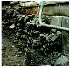
Figure 1. The existing
rubble foundation was sitting on well-drained soil and supported the building
adequately, but it was far too rough to accept the waterproofing membrane needed
to deflect heavy spring runoff.
Excavation and Cleanup
The first step was to rip out the remains of the old floor joists and cut away
the rotten part of the old wall studs in preparation for a floor slab that would
eventually be covered by sleepers and hardwood flooring. The rot was limited
to the portion of the studs that extended below the original floor, so once
the commercial flat-work sub was finished with the slab — which came to
the same height as the old wood floor — we just slipped in a new green-lumber
plate at the base of the balloon-framed finish wall. The flatwork sub also formed
and poured a new foundation for a shed that had originally extended off the
back of the building, which we would be replacing. Most of the timbers in the
exterior wall were sound, but we cut out and replaced a few rotten sections
near the back, where the grade was highest.
Backhoe archaeology. We dug the perimeter
trench with the backhoe attachment on our Kubota tractor. Only 6 feet wide,
it’s ideal for working in close quarters. An archaeologist sent by the
state wanted to examine the excavated material for artifacts, so we worked slowly,
raking carefully through the soil with the bucket before removing each scoop
of material. We’d hoped to turn up some hidden gold, but we didn’t
find much besides a few whiskey bottles and a silver-capped vial that still
held some sweet-smelling perfume.
Cleaning the stone. To reduce the risk of
damaging the wall by hitting large irregular stones, we also made a point of
keeping the bucket at least 8 inches away from it. The base of the wall barely
extended to the local 40-inch frost line, so we were also careful not to undermine
it by going too deep. On the plus side, this meant we didn’t have to worry
about shoring up the soil face of the excavation. After completing the main
trench, we peeled away the last of the dirt from the stone by hand.
Once we’d exposed the irregular rubble surface, we cleaned the remaining
dirt from the cracks and crevices with pointing tools before blowing them out
with compressed air. This involved striking a balance between removing as much
dirt and badly deteriorated masonry as possible without compromising the integrity
of the wall itself; it was one of the most time-consuming parts of the entire
job. It took us a full day to excavate and clean each of the 30-foot side walls.
We decided not to reinforce the back wall, which was in much better condition
to begin with and would be enclosed by the poured shed foundation. The front
foundation wall had been replaced years earlier, so from here on, we had only
the side walls to worry about.
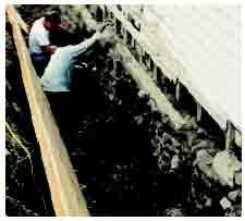
Figure 2. Wall forms
were made from 2x4s and full sheets of 3/4-inch plywood. Before they were secured
to the wall in preparation for the concrete pour, the forms were leaned back
against the side of the trench to help keep dirt out of the excavation while
the existing walls were being cleaned.
Site-Built Forms
After digging and carefully leveling the bottoms of the trenches, we’d
prepared some simple forms by placing full sheets of plywood end to end and
connecting them with 16-foot 2x4s scabbed together where they butted. These
were temporarily left leaning back against the bank, where they helped prevent
soil from spilling into the trench while we gave the stones their final cleaning
(Figure 2).
When the walls were completely clean, we leaned the plywood in toward the stone
to form a slightly tapered wall. We shot for an average wall thickness of about
4 inches, but because the existing foundation wall was so uneven, the forms
practically touched the stone in some areas and stood nearly a foot away from
it in others. Once we had the plywood in position, we secured it with horizontal
2x4 kickers running between 2x6 uprights screwed to the plywood and other uprights
pushed up against the bank on about 4-foot centers (Figure 3). The top edges
of the forms were 6 or 8 inches above the level of where the finished pour would
be, but there was enough space between the form and the rubble wall for us to
reach inside and snap a chalk line marking the level of the finished pour.
Site-Built Forms
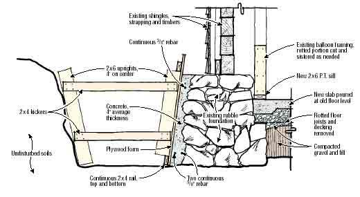
Figure 3. Horizontal
kickers secured the plywood forms to uprights pushed against the face of the
excavation. The existing rubble wall acted as the inner face of the form.
Repairing a Stone Foundation- continued
Rebar and bulkheads. For crack control, we
placed two strands of 3/8-inch rebar at the base of the wall and a single strand
at the top. The top of the wall stepped down in several places, and there we
formed bulkheads by scribing tapered blocks of 2x8 to fit tightly against the
stone and screwing it vertically to the inside of the forms. We used the same
method to fit the full-length bulkheads at the ends of the forms. Some dirt
packed along the bottom edge of the forms kept the concrete from leaking out.
Pouring the Concrete
We were confident that the thick stone walls could take the pressure of the
concrete. They weren’t very high to begin with, and the new interior slab
would prevent their bases from sliding inward. In contrast to the poor condition
of the exterior concrete — which had spent nearly a century underground
— the unweathered inner face was in decent shape. In a few areas, where
there were cracks or suspicious voids, we did some preliminary patching of the
wall from the outside using Sakrete and stones.
Conveyor and pea stone aggregate. Still, we
approached the actual pour cautiously. We didn’t want to use a pump, because
we needed only about 1 1/2 yards of concrete for each side, but we also needed
to control the flow carefully to avoid overfilling the forms. Instead, we used
a conveyor with a 36-foot reach, which was both cheaper and more accurate than
pumping would have been.
We specified a 3,000-psi fiber-mesh concrete with pea gravel aggregate in place
of the usual 1/2- or 3/4-inch stone. That helped the mix flow into the many
small voids in the old wall, which we encouraged by carefully vibrating the
concrete throughout the three or four lifts it took to fill the forms. We also
tapped the outside of the form with a hammer throughout the pour to encourage
the “gravy” to rise to the surface, leaving a nice smooth wall without
honeycombing. After placing the final lift, we troweled the top surface to slope
away from the building and rounded the outside edge to prevent it from damaging
the liner. Twenty-four hours later, we stripped the forms.
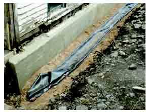
Figure 4. The new poured
wall locked the rubble in place and provided a smooth surface for a waterproofing
membrane. A smooth layer of roadbed material in the bottom of the trench helps
protect the membrane from punctures.
Waterproofing, Drainage, and Backfill
Because spring snowmelt exposes the repaired foundation to very heavy runoff,
we waterproofed it with a 40-mil EPDM membrane made by Carlisle (800/527-7092,
http://www.carlisleccw.com).
To prevent the membrane from being damaged by sharp stones, we started by lining
the trenches with a smooth layer of what’s locally called roadbed material
— a mixture of dirt, sand, and fine gravel — sloped gently to the
front for drainage (Figure 4).
After rolling out the 6-foot-wide material, we tacked it temporarily to the
siding at the top before cutting, fitting, and cementing it where it joined
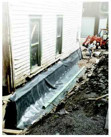
the poured addition at the back (Figure 5). Finally, we put down crushed stone,
drainage pipe, and filter cloth, topped by dirt from the site.
Flashing. Backfill tends to pull waterproofing
membrane down slightly as it settles, so I waited two months before I cut and
cemented the flap that covers the top of the new reinforcing wall (Figure 6).
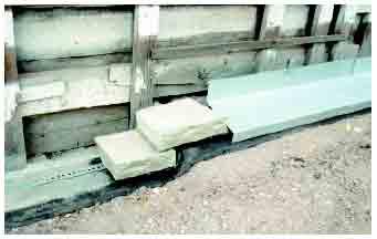
I’d originally hoped to cap the foundation with blocks of cut sandstone
known locally as farmer stone. In the end, though, the budget couldn’t
be stretched that far, so we finished up with a cap of 24-gauge galvanized flashing,
which was later tucked under the siding.
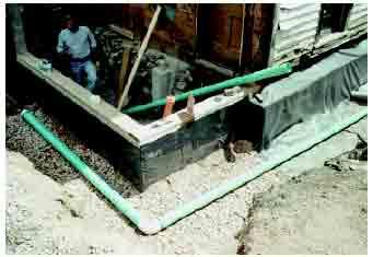
Figure 5. The 40-mil
EPDM membrane extends to the top edge of the new shed foundation but overlaps
the reinforcing wall, which lies outside the footprint of the building.
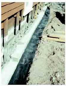
Figure 6. The topmost
edge of the membrane was left loose for two months to allow the backfill to
settle (above). After being cut and fitted over stepped sections of the foundation,
it was covered by galvanized flashing that was later tucked beneath the siding
(below).
Even so, this was a very cost-effective project. The total cost of the foundation
repair — including forming and pouring the new section of wall in back
and pouring the slab — came to about $4,800. That’s a fraction of
what it would have cost to jack up the building and pour a new foundation from
scratch. The rebuilt foundation is every bit as solid and watertight as a new
one would have been, while preserving the historic original.
David Rippe is co-owner, with Art Rombauer,
of R-3 Construction in Carbondale, Colo.
This article has been provided by www.jlconline.com. JLC-Online is produced by the editors and publishers of The Journal of Light Construction, a monthly magazine serving residential and light-commercial builders, remodelers, designers, and other trade professionals.
Join our Network
Connect with customers looking to do your most profitable projects in the areas you like to work.

