Business Articles - Specialty and Trade
Articles & Tips
Where lots are small and permit restrictions are tight, adding on often means adding down
by Bill Brown
Historically, few California houses have had basements. Virtually all of the
tract houses put up during the postWorld War II housing boom were built
on slabs or stem wall foundations, and so are most of today's new houses. But
in the past few years, more and more California homeowners have been showing
an interest in basements. Much of this has to do with increasingly restrictive
building permit conditions. In the area south of San Francisco, where I work,
many planning departments restrict building footprints to a specified percentage
of the building lot. Such floor-area ratio restrictions often make it impossible
for owners of existing homes to gain the floor space they want with a conventional
addition. At the same time, height restrictions designed to preserve existing
views may prevent them from raising the roof and adding another story.
Other than moving to a larger home, that leaves adding downward as the only
alternative for the homeowner who wants more space. Retrofitting a basement
isn't easy or inexpensive, but property values in the Bay area are high enough
to make it a practical option for many homeowners. My company, Bill Brown Construction,
specializes in high-end residential concrete work, and we have a well-established
system for adding basement living space without unnecessary disruption of the
site or the structure itself.
Design
Many of our projects result from word-of-mouth references. We then refer the
new clients to our preferred engineers and architects. Some of the time the
homeowners have already engaged a design team. The desire to retrofit a house
with a basement is generally the result of homeowners and their designer or
architect, in the process of designing a remodel, finding that the guidelines
set by their respective planning departments are too restrictive.
Every project we have worked on in the past 20 years here in the Bay area has
been required to be structurally designed by a licensed structural engineer.
A soils engineer provides a report that spells out the geological conditions
and recommends soil bearing pressures. The structural guys use the soils report
to generate the potential loads the structure will encounter.
It's interesting how much variation occurs in the opinions of structural engineers
on a residential basement design in similar soil conditions with the same soils
engineer. Give three engineers the same plans, and they will return three radically
different projects. That's why we like to be involved in the selection of the
engineering team if possible.
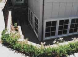
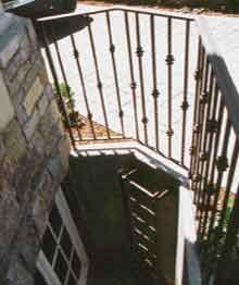
Figure 1. Retrofitted basements sometimes feature
extensive glazing combined with terraced gardens (above). In other cases, one
or more foundation wells -- equipped with permanent ladders and fenced for safety
-- provide minimal code-required egress and a modest amount of natural light
(right).
Not your father's basement. Some people want their basements to have
walkout patios with terraced gardens; others just want the minimum required
egress (see Figure 1). Minimum egress is all that's generally required by building
departments. Air and light requirements are usually met by the installation
of the egress well. This typically consists of window or door access to a pop-out
well with a ladder or stair to climb out. Most egress wells are covered by removable
steel grating or surrounded by a safety rail. A permanent ladder, fixed to the
wall, is often the means of getting into and out of the well. Each city or county
has guidelines for light, air, and egress, and they vary quite a bit.
Picking a structural engineer is critical for the success of the project. The
structural engineering should be done by someone familiar with the problems
regularly encountered when retrofitting, such as shoring, excavating in tight
quarters, subterranean waterproofing, and shotcrete applications.
Stitch Piers
OSHA rules for shoring or sloping vary for different soil conditions. A typical
basement excavation in reasonable soil will allow the lower 5 feet of the cut
to stand vertical without shoring, with the balance to grade sloped back at
a minimum of a 1-to-1 pitch. That's fine if you have the room, but it can be
a problem when the house has a narrow side or back yard setback. If the excavation
is 10 to 12 feet deep, for example, the back slope required is 5 to 7 feet --
an impossible demand when the setback is only 5 to 6 feet.
Because basement retrofits are most popular on tight lots, we see this kind
of problem often. Dealing with it involves shoring the face of the soil to permit
going down vertically for the full depth of the excavation. There are several
ways to do this, but the method we use most often involves placing a series
of concrete pilings, or "stitch piers," around the perimeter of the foundation.
In addition to shoring up the face of the excavation, the piers act as bearing
points for the steel beams that support the house during excavation. With properly
engineered stitch piers in place, we can excavate vertically right up to the
face of the piers. When the new basement is done, the stitch piers are no longer
needed and are usually cut off a foot or two below the level of the finished
grade.
Sinking the piers. As in all remodeling work, we have to deal with buried
utilities before we can start digging. The in-ground piping under an existing
house is normally limited to a sewer pipe, possibly a gas line at the perimeter,
and quite often an electrical conduit. The sewer is usually rerouted around
the excavation, or strapped to the joists for the duration of the project. We
simply cut sewer lines and reinstall them later, except when the client is planning
to stay in the house. The gas meter and supply line are most often removed during
construction. Local cities and counties require the line to be cut in the street
to prevent the excavation from filling with leaking gas and providing an untimely
and unwanted demolition of the house. Electrical conduits can be strapped to
the house or supported on a rack built for that purpose. We try to keep everything
functional if possible, for use during construction, and to avoid reconnection
fees.
Once we've taken care of the utilities, we drill holes just back from the building
line to a depth and spacing calculated by our structural engineer. (Because
we're in California, earthquake loads are factored in.) We usually use a drill
rig mounted on a small excavator to bore these holes, which are typically 18
to 24 inches in diameter (Figure 2). The holes extend to the depth of the excavation
plus the additional depth needed to resist the overturning force of the soil
outside the excavation. In many cases, that involves boring down 20 feet or
more.
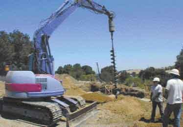
Figure 2. An excavator-mounted "dangle drill" is
used to bore holes for stitch piers. Bit extensions can be added as needed to
bore to depths of 25 feet or more. The drill rig can also be used to insert
rebar assemblies that are too heavy to move by hand.
That can be quite time consuming, especially if you hit a large rock that has
to be drilled out with a core drill.
If there's no way to bring in a drill rig, we sometimes have to hand-dig for
the piers. That's a specialized job that's actually done by miners who work
with specially engineered shoring. Needless to say, it's slower than drilling
and much more expensive.
In good soil, the uncased bore holes serve as forms for the piers. We usually
use four to six #5 rebar vertical reinforcing bars per pier, with a #3 stirrup
surrounding the vertical steel at 12 inches on-center. Once the steel has been
lowered into place, the holes are pumped full of concrete mix specified by the
engineer.
Jacking the House
The stitch piers are typically spaced 4 to 5 feet apart, allowing us to install
steel shoring beams on 8- to 10-foot centers, with every other pier acting as
a support for the end of a beam. Wherever possible, we use clear-span shoring,
which uses steel beams sized to support the full width of the structure without
intermediate supports. If the lot size permits sloping the face of the excavation
enough to avoid the need for stitch piers, we can often bear the beams on the
undisturbed soil beyond the excavation. That calls for longer beams, which increases
the required strength and adds to the difficulty of handling them.
Bringing in the beams. So far, all of our basement retrofits have involved
houses built on stem walls, because the cost of shoring a structure built on
a slab would exceed the cost of a new building. To prepare for installing the
beams, we send a crew out with jackhammers and a compressor to break holes in
the stem walls wherever beams are needed to support the structure. We take our
beams to the job on a 40-foot low-boy flat-bed truck. That can get pretty exciting
in a neighborhood with narrow streets. At the site we use heavy-duty rollers,
cribs, and pry bars to manhandle the beams into place.
Shifting the load. Transferring the structural load from the original
foundation to the temporary piers and beams is handled by our house-moving sub.
He positions a series of heavy-duty jacks under the beams and raises them little
by little. Instead of lifting the house -- which can crack finished surfaces
and rack openings out of square -- the goal is to transfer the structural load
without actually moving anything. This takes skill, practice, and a light touch.
Once the weight is taken by the beams, the beams are shimmed with hardwood wedges
or steel plates, and the jacks are removed until the new foundation is complete
(Figure 3).
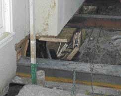
Figure 3.
The steel beams that temporarily support the structure are inserted into holes
that have been jackhammered through the stem walls. Once the beams have been
raised into position with jacks and shimmed into place, the jacks are removed
and the original foundation is demolished.
Excavation
Our company owns five Bobcat skid-steer loaders, which allows us to do most
of our own excavation work. Their ability to turn 360 degrees in their length
is essential in the tight quarters under a house. With the available attachments,
we find that we can do almost any job that requires heavy lifting, trenching,
or mass excavating.
Dealing with fill. We start the excavation by digging a ramp in the direction
of the house at a point that offers the best angle of attack. If possible, we
like to cut the ramp with an excavator that has the ability to spin 180 degrees
and load a truck directly behind itself. Once the ramp is done, the skid-steers
can begin cutting a slot into the soil under the house. As the hole gets bigger,
the skid-steers feed the soil to the ramp for the excavator to load into trucks
for transport to a landfill or other projects requiring fill (Figure 4). In
some cases, we park a small excavator at the top of a light well or other opening
to bail the dirt out as the skid-steer unit or units push the soil to it.
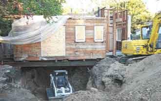
Figure 4. Tracked skid-steer loaders are preferred
for working beneath the house because they're highly maneuverable and provide
excellent traction. The skid-steer pushes the excavated soil to an opening,
where it's scooped up by an excavator and loaded into a waiting dump truck.
Crib shoring. When the layout of the site doesn't permit us to bring
in beams long enough to use free-span shoring, we sometimes have to resort to
crib shoring instead. A typical crib is a square wood frame about 2 feet high,
with internal diagonal braces. Such frames are stacked below wood or steel beams
to provide support where needed (Figure 5).
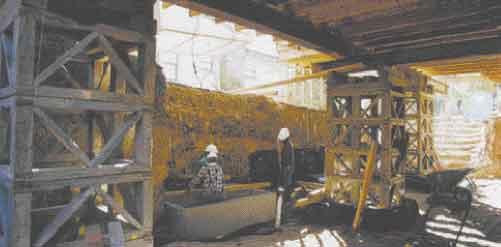
Figure 5. Where full-length shoring beams are impractical,
shorter beams are supported by cribwork as needed. No stitch piers were required
to support the solid soil forming the face of the excavation shown here. The
concrete vault will eventually house a sump pump.
When we're using cribs, the excavation becomes a real chore. At the start of
a project, the soil level is typically 18 inches to 2 feet under the bottom
of the joists. When the shoring beams are installed, they're supported on stacked
timber and jacks in the crawlspace. The beams are initially very close to the
ground, so digging must begin in an area where there are no cribs or jacks.
Once we've created a slot between the cribs or jacks to a safe working depth,
we have to take time to "jump the crib" -- placing a new intermediate support
before removing the crib in the previously unexcavated area. Digging out a large
foundation in this way can take weeks, compared to just a few days if clear-span
shoring is used.
Structural Slabs
In the San Francisco Bay area, most municipalities and counties are concerned
about earthquakes. The 1989 Loma Prieta quake and the more recent Northridge
shake in Southern California have given engineers many examples of failed steel-reinforced
concrete to analyze. Earthquake concerns, coupled with the geological conditions
in the area, contribute to a conservative approach by structural engineers.
Steel configurations for residential installations resemble those that just
a few years ago would have been used for light to heavy commercial or public
works buildings.
In many instances, that involves a "mat slab" footing design rather than a conventional
cantilevered slab, which is thickened only where needed to provide a footing.
A typical mat slab is 10 to 12 inches thick throughout, although we have poured
some slabs up to and beyond 20 inches thick. This may seem like a bit much for
a residence, but here in California people tend to litigate, and we have to
cover our backsides in order to remain in business.
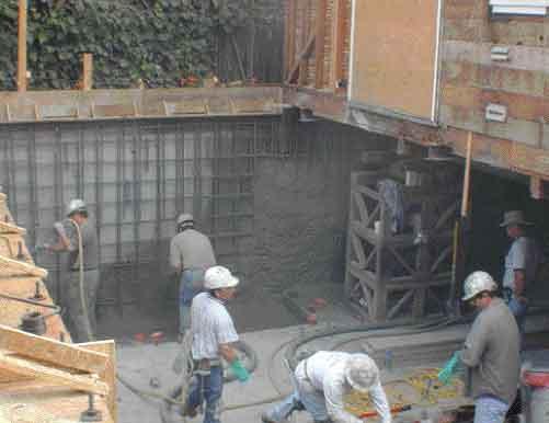
Drainage and waterproofing membrane. Our basements are meant to provide
dry, high-quality living space, so we take great care to drain and waterproof
the area before pouring the slab. The drainage systems we feel the most comfortable
with are multilayered to resist groundwater as well as surface seepage (Figure
6).

Figure 6. The author's multilayered foundation
waterproofing system ensures a dry basement and can be adapted to formed shotcrete
walls or walls that are gunned against the excavation without backfill.
The first step in this process is to shape the sub-slab grade to a slight slope
toward a drainage sump below the level of the basement floor. We often use reinforced
concrete pipe set vertically for the sump walls, because the float switches
on our preferred pumps need a space of 12 to 16 inches to function properly
(Figure 7).
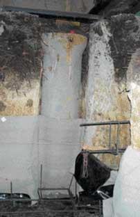
Figure 7. A reinforced concrete pipe set into a
groove cut into the excavation face provides a drainage sump that lies outside
the living space. The turned-up edge of the slab waterproofing membrane covers
the lower section of the pipe, which will later be covered by a reinforced shotcrete
wall.
A grid of drainage pipe enclosed in polyester sock material is placed on the
gently sloping grade. This is followed by a layer of crushed stone, a protective
layer of filter fabric, and a waterproofing membrane. Our favorite material
for this application is a product called Paraseal (Tremco, 800/321-7906, http://www.tremcosealants.com),
which is a flexible, high-density polyethylene membrane with a layer of bentonite
-- a highly expansive clay-like mineral -- adhered to one side. If any water
makes it past the outer layer of poly, it liquifies the bentonite, which is
forced into the pores of the concrete and swells to provide a reliable seal.
One of the greatest advantages of using bentonite is that you can apply it to
uncured concrete without a warranty problem. The product does not rely on a
chemical bond for its performance.
When we use Paraseal under a floor slab, the material is laid bentonite side
up over the drainage mat. The material comes in 4x24-foot rolls, so we overlap
it 2 inches where necessary and staple the seams with a box stapler to keep
them in position while the concrete is poured. The pressure of the concrete
causes the material to seal to itself at the laps. We leave plenty of extra
material around the perimeter to ensure a good bond to the membrane that will
later be placed behind the walls (Figure 8).

Figure 8. A two-layer rebar grid reinforces the
structural slab against seismic loads and eliminates the need for pad footings
beneath point loads. After the slab has been poured, drain mat and waterproofing
membrane will be applied to the face of the excavation -- which has been stabilized
with stitch piers -- and shotcrete will be gunned against the bank. The above-grade
portion of the wall will be backed by a single-sided form. To avoid puncturing
the slab membrane with grade stakes, the screeds that will be used to level
the slab are supported with temporary lumber braces nailed to the overhead joists.
Rebar and utilities. Once we've rolled out and secured the waterproofing,
we lay out the reinforcing steel, plumbing, ductwork, and electrical conduit.
A typical mat slab steel configuration consists of a double layer of #5 steel
at 12 inches on-center; at the perimeter walls, a vertical #5 or #6 rebar dowel
will protrude 3 to 4 feet out of the slab at 4 to 6 inches on-center.
During this stage, it's essential to minimize any staking through the membrane
for screeds or bracing. If it becomes absolutely necessary to penetrate the
Paraseal, a liberal dose of Paramastic -- a proprietary sealant designed to
be compatible with the Paraseal -- must be smeared around the stake. Finally,
the slab is poured and finished in the usual way.
Basement Walls
Where possible, we'll often place the stitch piers or other shoring several
feet outside the final location of the basement wall. That leaves room for conventional
two-sided concrete forms and lets us install poured foundation walls with conventional
waterproofing, perimeter drains, and crushed-stone backfill.
On many tight lots, though, there simply isn't enough room to form and pour
foundation walls. In those cases, we use shotcrete -- a high-quality sprayed
concrete that minimizes form work and can be applied even in tight quarters.
Single-sided forms. One approach to placing shotcrete involves forming the outside
surface of the wall with single-sided snap-tie forms, placing the rebar grid
on the inside, and applying the necessary thickness of shotcrete (Figure 9).
The amount of steel specified will vary with the preference of the engineer,
the height of the wall, and the local soil conditions. A single grid of #5 steel
at 12 inches on-center is fairly typical, but some walls call for two or even
three times that much steel. Unless it is very high, a shotcrete wall is usually
8 to 12 inches thick.
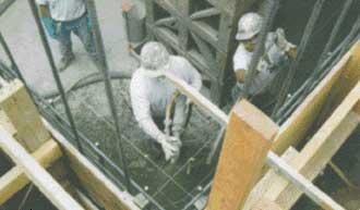
Figure 9. Gunning shotcrete against a single-sided
form, rather than directly against the excavation, provides space for stone
backfill and affords more control over the waterproofing on difficult sites.
Once the single-sided forms have been stripped, we waterproof the walls with
a layer of Paraseal, which laps over and outside the Paraseal turned up beneath
the floor slab. The Paraseal is protected by a layer of dimpled drain mat (Figure
10). Finally, we put down a fabric-wrapped perimeter drain and backfill with
crushed stone to within about 2 feet of the finished grade. We use a clay-type
soil for the topmost portion of the backfill to resist infiltration of surface
water.
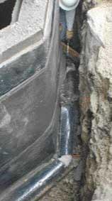
Figure 10. Formed shotcrete walls are waterproofed
with a layer of Paraseal membrane -- visible near the top of the wall -- followed
by dimpled drain mat. The upper edge of the drain mat will be secured with a
termination bar provided by the manufacturer. The worker visible at top is standing
in an excavated void reinforced with stitch piers.
Formless shotcrete. On sites with good natural drainage, it's sometimes
possible to do away with forms altogether by spraying shotcrete directly against
the wall of the excavation. This also does away with the need to backfill, but
it requires a different approach to waterproofing: Instead of a waterproof membrane
applied to the outer surface of the wall, it involves pinning the drainage mat
and membrane to the face of the excavation, placing the rebar, and shotcreting
over it to the required thickness.
If we're going to be using that approach, we take special care during the excavation
phase, so we're left with smooth, flat walls. We've found that broken snap-tie
pins work well to secure the waterproofing and drainage mat to the soil. Like
punctures beneath the slab, these snap-tie penetrations are waterproofed with
a bentonite sealant.
Structural Supports
Some structural upgrading is often needed when a house is retrofitted with a
basement. At minimum, we have to replace the existing interior concrete stem
walls with a new support system. We use steel beams for that purpose most of
the time. The mat-slab foundation simplifies the process, because there's no
need to use pad footings for interior point loads -- the floor slab is capable
of bearing point loads anywhere. Sometimes we install new I-joists if we're
increasing the span or if the old joists are undersized. Typically, the old
joists are left in, and the new joists are sistered to them.
Lowering the jacks. Before we shotcrete in the new foundation walls,
we secure a new mudsill to the existing floor system, complete with new bolts
and hold-downs. The new mudsill acts something like a plaster ground as the
shotcrete wall is sprayed up against it.
When the concrete reaches an acceptable strength, the jacks are lowered, allowing
the beams to settle into blocked-out pockets in the new foundation and transferring
the structural load to the new basement walls.
Finishing up. At this point, there's still plenty of work to do. There's
usually some finish cracking to repair on the original structure, and many of
our customers hire a general contractor to finish their new basement as additional
living space, occasionally including amenities such as wine cellars and home
theaters.
But once the jacks and beams are removed and the beam pockets have been closed
up, our job is done. The T-shirts our crews wear say it all: "We Do the Hard
Part."
Bill Brown is a specialty concrete and general contractor in Saratoga,
Calif.
This article has been provided by www.jlconline.com. JLC-Online is produced by the editors and publishers of The Journal of Light Construction, a monthly magazine serving residential and light-commercial builders, remodelers, designers, and other trade professionals.
Join our Network
Connect with customers looking to do your most profitable projects in the areas you like to work.